ShowCAD Control Systems Users
As a user of a registered version of ShowCAD Artist3 we invite you to a free upgrade to use our product.
Our ShowCAD 4 is compatible with Artist3. To maintian support for Artist3 you must
install ShowCAD 4.
To proceed, create a free account and discover more. This is a one-way process.
Once ShowCAD4 is installed Artist3 can no longer be used.
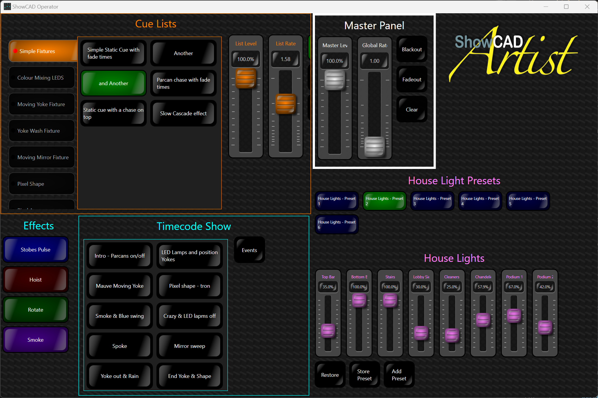
ShowCAD has been developed for many years and found favour for show control across entertainment venues, architectural settings, and diverse public arenas. The software is designed to handle projects of any magnitude, offering unparalleled flexibility and dependability.
Engineered for environments demanding sequential control and extensive connectivity, the software seamlessly integrates into a myriad of operational contexts.
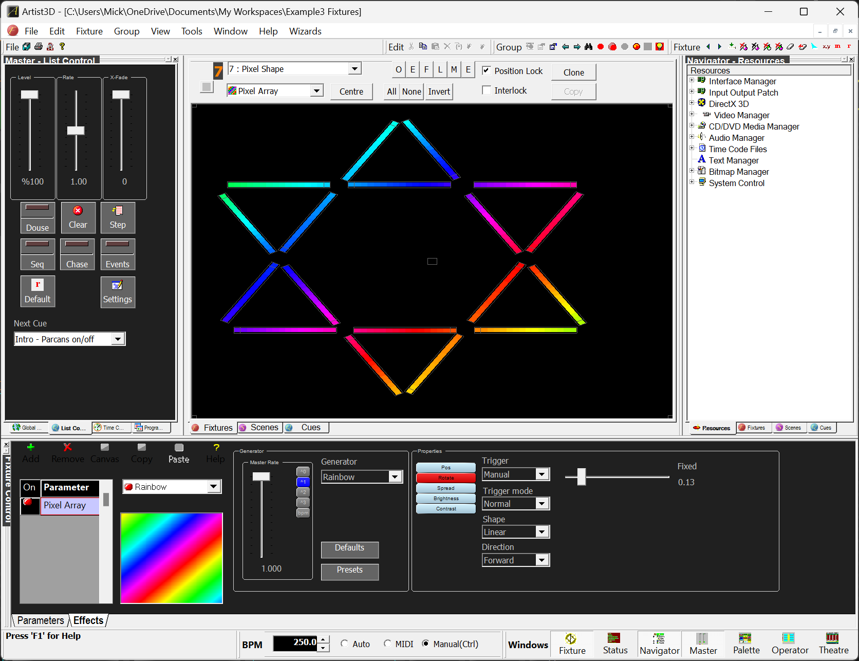
Due to its connectivity, ShowCAD is well suited to acting as the central hub of a lighting and sound system connecting easily to other systems like laser controllers and pixel controllers.
Connecting to the outside world is its super-power. All manner of device can be connected to our software now - LED matrixes, audio recognision, visualisers, remote control panels, web apps, IoT.
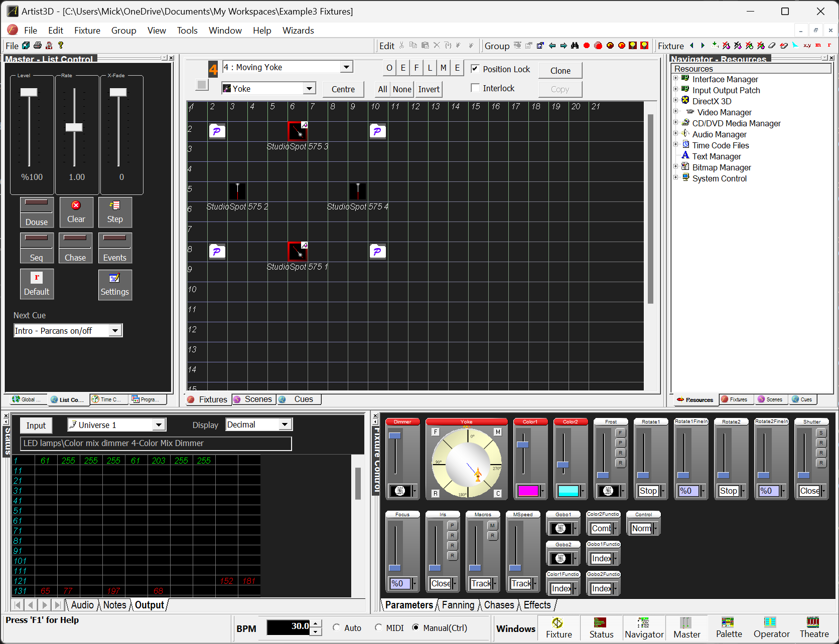
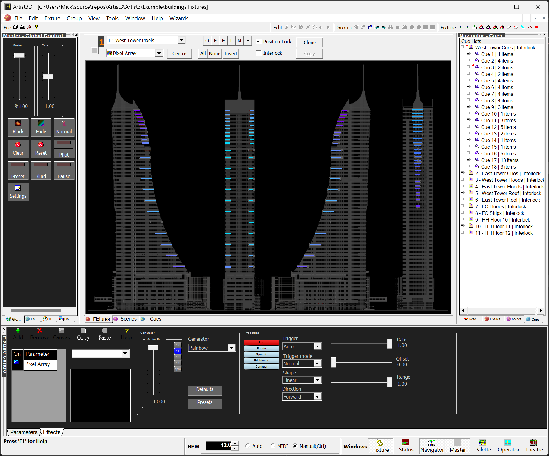
ShowCAD controls all types of DMX lighting fixtures; fixed spots and par cans, moving lights, video, audio, pixel tape, projectors and other sub-system controllers
Configurable remote panels give multiple remote points of access to the system functionality.